
Best Practice: Executable Stack-Ups (Maßkette) in KCL
1The engineer's anchor: the dimension chain
Every mechanical engineer carries the same mental model into an assembly: the stack-up, or Maßkette — the chain of dimensions that adds up, segment by segment, to the total of the machine. Not primarily as tolerance analysis, but as the fundamental bookkeeping of design: this part contributes 51 mm, that one 12, the stroke adds 180, and it all must close on 442.
- Standard parts contribute fixed catalog dimensions.
- Custom parametric parts absorb the variation.
- One closing dimension ties the whole thing together — and when the design changes, the chain is the first thing a reviewing engineer checks.
Traditional GUI CAD systems respect this model poorly. The chain lives half in the modeler's hidden equation tables and half in an Excel sheet beside the CAD, silently drifting out of sync with the geometry. Parts are positioned by mating them to other parts, in fragile chains where the causality — which dimension drives which — is invisible.
This paper describes a best practice for making the Maßkette the executable master of a design in KCL, the parametric CAD language of Zoo Design Studio. Everything in sections 2–5 runs in current KCL 2.0 today, with no new functionality. Section 6 adds one clearly marked proposed extension — plane-anchored dimensions — that turns the audited chain into the drawing.
The method is demonstrated on a hydraulic cylinder throughout, in two figures: first as a single assembly, then split across sub-assemblies.
2The Maßkette as executable code
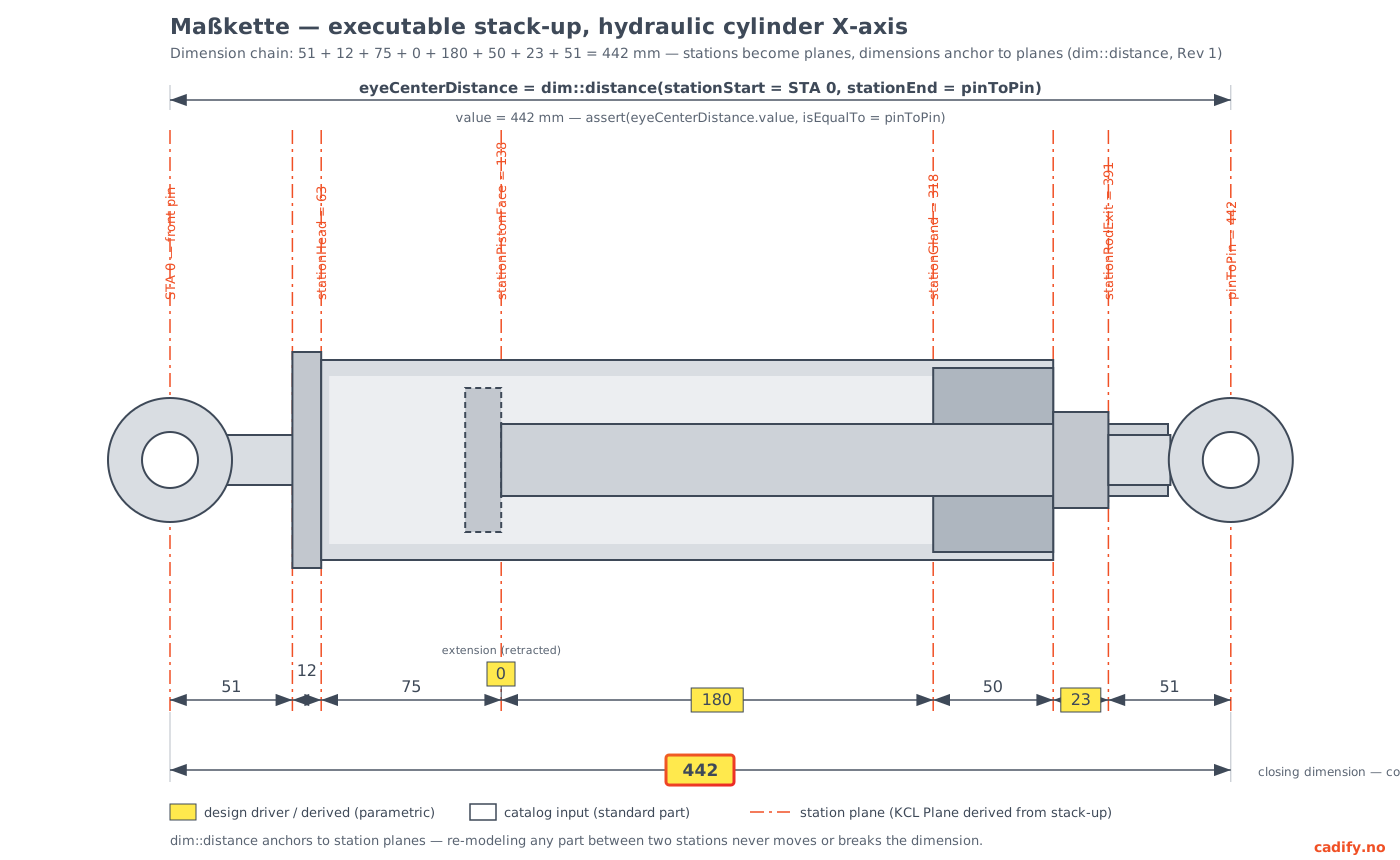
dim::distance of section 6.Read Figure 1 from the bottom up, because that is the order in which the design is actually built:
- The chain is the master. Each segment is owned either by a standard part (fixed, from a supplier catalog — white) or by the design itself (drivers such as the stroke, and derived values — yellow).
- The stations are the running sums of the chain: 0, 51, 63, 138, 318, 368, 391, 442. Each named station becomes an ordinary KCL plane.
- The geometry hangs off the stations. Parts and sub-assemblies are positioned on station planes — never on each other.
- The closing dimension (442) is computed from the chain
and checked by an
assert. If any segment drifts, the model stops compiling and tells you which requirement broke.
In code, the entire chain is one small module. This is the heart of the practice:
// ── stackup-x.kcl ── the X-axis Maßkette, and nothing else ──
@settings(kclVersion = 2.0)

// Catalog inputs (standard parts) — white in Figure 1
export rodEyeFront = 51mm
export headCap = 12mm
export pistonZone = 75mm
export glandLength = 50mm
export rodEyeRear = 51mm

// Design drivers — yellow in Figure 1
export stroke = 180mm
export extension = 0mm // current state: retracted
export spacer = 23mm

// Derived stations: running sums from the front pin center
export stationHead = rodEyeFront + headCap
export stationPistonFace = stationHead + pistonZone + extension
export stationGland = stationPistonFace + stroke
export stationRodExit = stationGland + glandLength + space
export pinToPin = stationRodExit + rodEyeRea

// Derived part dimensions: the custom parts absorb the drivers
export tubeLength = pistonZone + stroke + glandLength // = 305mm
export rodLength = stroke + glandLength + spacer // = 253mm

// Closing dimension: computed once, never typed twice
assert(pinToPin, isEqualTo = 442mm, error = "pin-to-pin drifted from spec")
Two properties of this module deserve emphasis, because no GUI CAD system offers either.
First, the stack-up is re-audited on every compile: the
assert is not documentation, it is enforcement.
Second, causality is readable in the file: a reviewer sees at a glance which numbers are supplier facts, which are design decisions, and which are consequences. That is precisely what a signing engineer needs to verify, presented in the format they already think in.
3Conventions
The practice depends on a handful of hard conventions. They are deliberately strict — a design that follows them can be navigated, reviewed, and safely modified by any engineer or AI assistant without further explanation.
- One stack-up module per axis, named
stackup-x.kcl,stackup-y.kcl,stackup-z.kcl. The module contains parameters, derived values, and asserts — never geometry. - Order within the module is fixed: catalog inputs first, then design drivers, then derived stations, then derived part dimensions, then asserts. The file reads as the chain reads.
- Stations are named with the
stationprefix (stationGland,stationPistonFace), in camelCase, and are always running sums from a single, stated datum (here: the front pin center at station 0). - Every total is derived, never typed. A number that can
be computed from the chain must be computed from the chain. The closing
dimension appears as a literal exactly once — inside its
assert. - The chain is plain arithmetic. Never place chain values
inside sketch-solve
varinitial guesses (KCL requires guesses to be literals in any case); fixed values belong in constraint arguments, and architectural values belong in the stack-up module. The Maßkette must stay deterministic — that is its purpose. - Parts reference stations, never each other. If you find yourself measuring one part to position another, the missing station belongs in the stack-up module.
4Stations become planes; sub-assemblies mount on stations
The stations turn into geometry anchors with one existing function. In the top-level assembly:
// ── main.kcl ─────────────────────────────────────────────
@settings(kclVersion = 2.0)
import stationPistonFace, stationGland, pinToPin from "stackup-x.kcl"

leftEyeCenterPlane = offsetPlane(YZ, offset = 0)
pistonFacePlane = offsetPlane(YZ, offset = stationPistonFace)
glandPlane = offsetPlane(YZ, offset = stationGland)
rightEyeCenterPlane = offsetPlane(YZ, offset = pinToPin)

// Sub-assemblies compile in isolation and mount on stations
import "tube.kcl" as tube
import "rod.kcl" as rod
Each sub-assembly is its own file, consuming the same stack-up module fo the dimensions it owns. This is where the practice pays off.
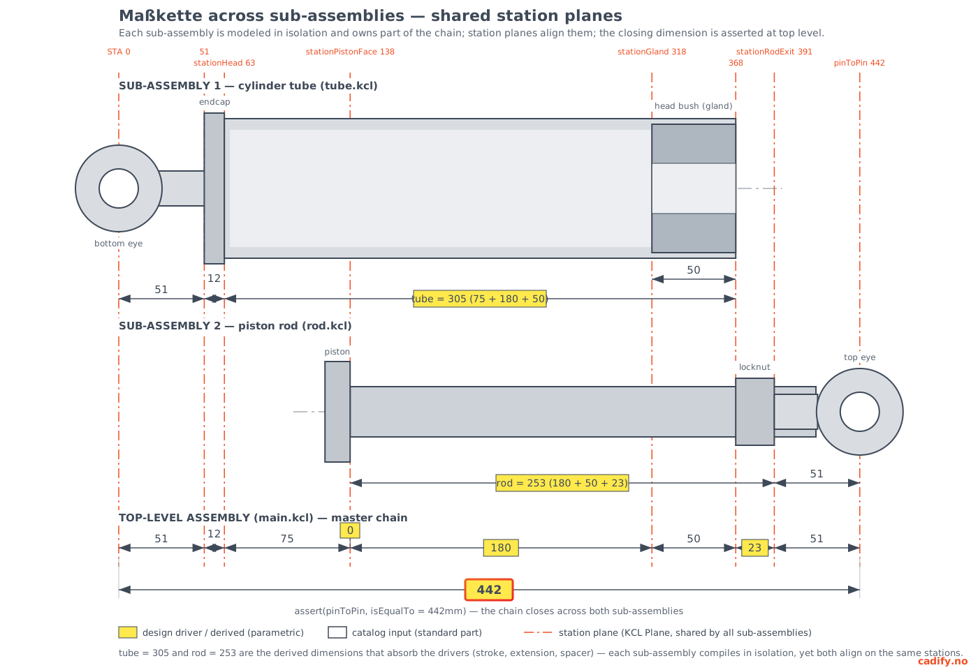
tube.kcl) — bottom eye,
endcap, tube, head bush — owns the internal chain 51 + 12 + tube, where tube
= 305 (= 75 + 180 + 50) is the derived dimension absorbing the drivers.
Sub-assembly 2 (rod.kcl) — piston, rod, locknut, top eye — owns
rod = 253 (= 180 + 50 + 23), its piston face sitting exactly on
stationPistonFace. The master chain closes on the asserted 442,
across both sub-assemblies.Figure 2 shows three properties that part-to-part mating cannot express:
- Isolation. Each sub-assembly is modeled in its own file
and compiles independently — Zoo executes modules in parallel — and can
be validated and signed off as a unit. Nothing inside
tube.kclreferences anything insiderod.kcl. Once signed off, a sub-assembly is a trusted black box; only its stations matter to the outside. - Shared causality. The drivers live once, in
stackup-x.kcl, and both sub-assemblies consume them: the stroke appears inside tube = 305 and inside rod = 253. A parameter that two sub-assemblies jointly depend on is one line in the stack-up module — mating cannot say that at all. - A closing audit across the boundary. The master chain closes on 442 across both sub-assemblies. Whether drift comes from a supplier revising the head bush or an engineer re-designing the rod, the assert catches it at compile time, before it reaches a drawing or a purchase order.
Change the stroke from 180 to 200 and watch the practice work: both yellow derived dimensions re-derive (tube = 325, rod = 273), every station beyond the piston face moves, both sub-assemblies rebuild in their new positions — and the closing assert fails loudly until the specification is consciously updated. That failure is not an inconvenience; it is the design review.
5What this replaces
In a mate-based assembly, the cylinder above would be built as a chain of constraints: eye mated to cap, cap to tube, tube to gland, gland to rod. Each mate is locally reasonable; collectively they hide the architecture. The wheelbase question — "what adds up to 442, and who owns each contribution?" — has no home in the model and migrates to a spreadsheet.
In the stack-up practice, that question is the model. The chain is version-controlled text, diffable in git, reviewable line by line. The stations are the single source of positional truth. And because the whole arrangement is deterministic arithmetic — no solver, no constraint ordering — the same inputs produce the same machine, every time, which is what "sign-off" is supposed to mean.
6From audited chain to drawing: dim::distance (proposed syntax)
Status note. Everything above this section
is current, working KCL 2.0. This section uses proposed
standard-library functionality — dim::distance and
dim::show — specified in the companion document
"KCL Model
Dimension Syntax Rev 1" (Cadify, 2026-07-08) and offered as an open-source
contribution toward Zoo's roadmap item "Drawings & GD&T." It does not
run in Zoo Design Studio today, and AI assistants applying this paper should
not emit it into production models until it ships.
The chain in stackup-x.kcl is the audit; the stack-up drawing —
the printable, signable sheet of Figure 1 — is still manual. The missing
primitive is a dimension that is anchored to station planes rather than to
model topology:
eyeCenterDistance = dim::distance(
  name = "eyeCenterDistance",
  label = "Eye center distance",
  stationStart = leftEyeCenterPlane,
  stationEnd = rightEyeCenterPlane,
  precision = 0,
  tolerance = 1mm,
)

// The annotation and the audit are the same object
assert(eyeCenterDistance.value, isEqualTo = pinToPin)

// Presentation is separate from measurement — per view, restyled freely
dim::show(
  eyeCenterDistance,
  displayPlane = XZ,
  level = "outer",
  textOrientation = "top",
  textPosition = "inside",
  fontSize = 10mm,
)
Two design decisions matter. The dimension returns its evaluated value, so the number shown on the released drawing and the numbe checked against the stack-up are the same object — re-verified on every compile. And the dimension anchors to planes, not topology: re-model any part between two stations, replace a supplier component, regenerate a part with Text-to-CAD, and the dimension neither moves nor breaks. It inherits the black-box property of Figure 2's sub-assemblies at the annotation level.
With this primitive, the bottom rows of Figures 1 and 2 stop being illustrations and become output: the Maßkette rendered from the model itself, exportable to DXF or PDF on a standard sheet — the executable paper trail, closed end to end. Until it ships, the practice of sections 2–5 already delivers the audit; the drawing is produced conventionally from the same numbers.
7Adoption checklist
To apply this practice to a new design in Zoo Design Studio:
- Identify the principal axes and write one
stackup-<axis>.kclper axis, in the fixed order of section 3, with the closing dimension asserted. - Derive station planes in
main.kclwithoffsetPlane, one per named station. - Give each sub-assembly its own file; import shared dimensions from the stack-up module; mount everything on stations.
- Add an
assertfor every dimension a reviewer would check by hand — closing dimensions, critical clearances, interface positions. - Keep the project in git. The stack-up module's diff is the engineering change note.
The result is a design in which the document engineers already trust — the stack-up — is no longer a description of the model. It is the model.
Companion document: Zoo Dev Contribution Spec Rev 1: KCL Model Dimension Syntax — dim::distance