
KCL Model Dimension Syntax — dim::distance
| Rev | Date | Change |
|---|---|---|
| 0 | 2026-06-09 | Initial four-plane dimension model and dim::distance
syntax proposal. |
| 1 | 2026-07-08 | Restructured around the Maßkette (dimension chain) as the anchoring
concept, with two new illustrations. Measurement and presentation
separated into two functions. Return value defined. Plane-model
semantics made precise. Relationship to the existing gdt::
module resolved. All syntax aligned with current KCL 2.0. |
1Why this revision
Rev 0 established the right foundation: a dimension must be defined independently of any drawing, viewport, or output format, and it must be anchored to reference planes, not to model topology (edges, vertices, faces). Plane anchoring means a dimension survives complete re-modeling of the parts between its anchors.
Two things drove this revision.
First, Rev 0 contradicted its own core principle. The
introduction demanded view independence, but the proposed
dim::distance call embedded presentation state —
displayPlane, fontSize, textOrientation,
textPosition, level, show — directly in
the dimension definition. A dimension defined that way cannot appea
differently in a 3D viewport and on an A3 sheet, which was the entire point.
Rev 1 separates the two concerns: dim::distance defines the
measurement; a new function, dim::show, defines the
presentation.
Second, and more important: we found the argument that makes this
proposal land. The dimension chain — the Maßkette — is the mental
anchor of every mechanical engineer. It is how the total of an assembly is
understood as the sum of its parts: catalog dimensions from standard
components, derived dimensions from custom parametric parts, and one closing
dimension that everything must add up to. Rev 1 is built on two illustrations
of a hydraulic cylinder that show the Maßkette living natively in KCL — first
in a single assembly, then across sub-assemblies. The
dim::distance proposal is presented as what it really is:
the last missing piece that turns this already-working
discipline into the drawing.
2The Maßkette in KCL — one assembly
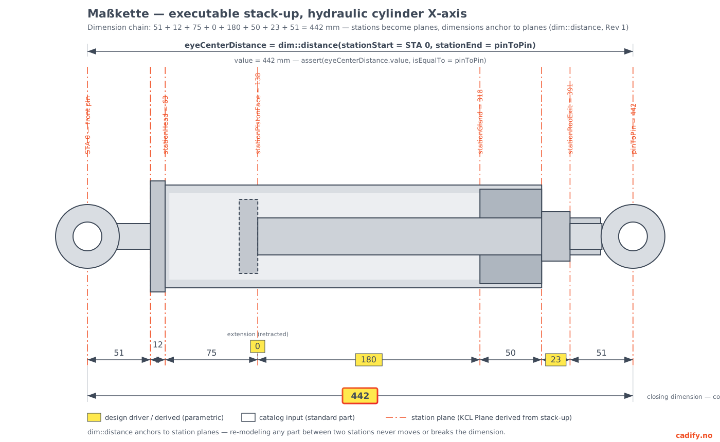
Plane objects derived from the chain's running sums
(stationHead = 63, stationPistonFace = 138, stationGland = 318,
stationRodExit = 391, pinToPin = 442). White dimensions are catalog inputs
from standard parts; yellow dimensions are design drivers and derived values.
The 442 is the closing dimension: computed once, never typed twice, asserted
on every compile. Across the top, the proposed dim::distance
measures between the first and last station planes — the annotation and the
audit are the same object.Figure 1 shows the discipline this spec serves. The chain along the bottom is the classic engineering stack-up: each segment is owned either by a standard part (fixed, from a supplier catalog — shown white) or by the design (drivers and derived values — shown yellow). The running sums of the chain define stations, and each station becomes an ordinary KCL plane.
Everything below the dimension line in Figure 1 works in KCL today, with no new functionality:
- The chain is plain arithmetic in a parameters module — deterministic, readable, auditable.
- Stations become planes with the existing
offsetPlanefunction. - The closing dimension is enforced with the existing
assertfunction, re-verified on every compile.
What does not exist today is the dimension drawn across the top of
Figure 1: a dimension defined between two planes, carrying an evaluated value,
displayable in any view. That is what dim::distance adds.
3The Maßkette across sub-assemblies
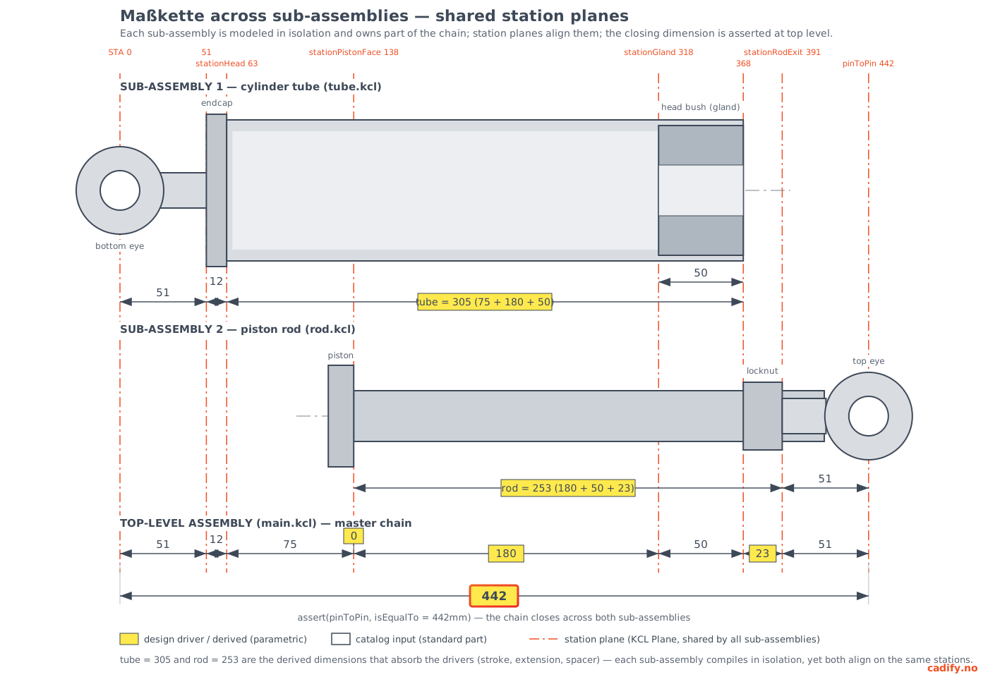
tube.kcl): bottom eye,
endcap, tube, and head bush, with its internal chain 51 + 12 + tube, where
tube = 305 (= 75 + 180 + 50) is the derived dimension absorbing the drivers.
Sub-assembly 2 (rod.kcl): piston, rod, locknut, and top eye,
with rod = 253 (= 180 + 50 + 23) as its derived dimension, the piston face
sitting exactly on stationPistonFace. At the bottom, the
top-level master chain closes on the asserted 442 — across both
sub-assemblies.Figure 2 is the payoff. The station planes run unbroken through both sub-assemblies and the master chain — because they belong to the stack-up, not to any part. This gives three properties no mate-based CAD assembly can offer:
- Isolation. Each sub-assembly is modeled in its own file,
compiles independently, and can be validated and signed off as a unit.
Nothing inside
tube.kclreferences anything insiderod.kcl. - Shared causality. The drivers (stroke 180, extension 0, spacer 23) live once, in the stack-up module. Both sub-assemblies consume them: the stroke appears inside tube = 305 and inside rod = 253. Part-to-part mating cannot express a parameter that two sub-assemblies jointly depend on; a shared chain expresses it in one line.
- A closing audit across the boundary. The master chain closes on 442 across both sub-assemblies, and the assert catches any drift — whether it comes from a catalog part revision in the tube or a rod re-design.
A dimension anchored to station planes inherits all three properties. Re-model any part between two stations — replace a supplier's head bush, regenerate the rod with Text-to-CAD — and the dimension neither moves no breaks.
4Scope
This spec proposes new KCL standard-library
functionality. It is not current Zoo syntax. It targets Zoo's public
roadmap item "Drawings & GD&T — production-ready 2D output"
and is intended as a contribution to the open-source KCL effort (KittyCAD
modeling-app).
In scope: linear distance dimensions between parallel reference planes, their evaluated values, and their presentation in a display plane. Out of scope for Rev 1 (see §11): angular, radial, and diametral dimensions; asymmetric tolerances and fits; chained/ordinate dimension groups; the DXF/PDF sheet-rendering pipeline.
5Design principles
- View independence. A dimension is a fact about the product, not about a drawing. Definition and presentation are separate constructs.
- Plane anchoring. Dimensions attach to abstract
Planeobjects — the station planes of Figures 1 and 2 — never to topology. - Executable value. Every dimension evaluates to a numbe
that can be asserted, exported, or reused. A dimension that cannot be
checked by
assertis not finished. - Native KCL style. Keyword arguments, unit-aware numbers,
namespaced module functions, the documented
Planetype. No new syntax forms — only new standard-library functions.
6The measurement model
A distance dimension is defined by three planes (Rev 0's fourth plane, the display plane, now belongs to presentation, §8):
| Plane | Role |
|---|---|
stationStart |
Reference plane where the measurement begins. |
stationEnd |
Reference plane where the measurement ends. |
measurementPlane |
(optional) Plane in which the distance is evaluated. |
Semantics. stationStart and
stationEnd must be parallel; if not, execution fails with an erro
(consistent with assert behavior). The evaluated value is the
perpendicular distance between the two station planes — the distance between
their origins projected onto the shared normal. When
measurementPlane is omitted it defaults to any plane containing
that normal; it exists to make the measurement direction explicit when the
station planes carry more orientation than the dimension needs.
Station planes are ordinary KCL Plane values: standard planes
(XZ), derived planes
(offsetPlane(YZ, offset = station)), or custom planes
({origin = ..., xAxis = ..., yAxis = ...}). No new plane machinery
is required.
7dim::distance — defining a measurement
eyeCenterDistance = dim::distance(
  name = "eyeCenterDistance",
  label = "Eye center distance",
  stationStart = leftEyeCenterPlane,
  stationEnd = rightEyeCenterPlane,
  measurementPlane = cylinderAxisPlane,
  precision = 0,
  tolerance = 1mm,
)| Argument | Type | Required | Description |
|---|---|---|---|
name | string | Yes | Stable identifier for code, export, and PLM traceability. |
label | string | No | Human-readable text. Defaults to name. |
stationStart | Plane | Yes | Start reference plane. |
stationEnd | Plane | Yes | End reference plane. Must be parallel to
stationStart. |
measurementPlane | Plane | No | Plane in which the distance is evaluated (§6). |
precision | number | No | Decimals shown when presented. Default per project settings. |
tolerance | number (Length) | No | Symmetric ± tolerance. Reserved for extension to asymmetric limits and fits (§11). |
Returns: Dimension — an object with at
least:
| Field | Type | Description |
|---|---|---|
value | number (Length) | The evaluated distance, computed at execution time from the current geometry. |
name, label | string | As defined. |
tolerance | number (Length) | As defined. |
Because value is a plain unit-aware number, dimensions compose
with the rest of KCL:
assert(eyeCenterDistance.value, isEqualTo = 442mm, error = "pin-to-pin drifted from spec")This is the property no GUI CAD system offers, and it is the headline of this proposal: the dimension on the released drawing and the checked dimension in the stack-up audit are the same object, re-verified on every compile. In Figure 1 this is the dimension across the top; in Figure 2 it is what closes the chain across two independently compiled sub-assemblies.
8dim::show — presenting a measurement
Presentation attaches to an existing Dimension and neve
changes what is measured. The same dimension may be shown in several views with
different styling, or not shown at all.
dim::show(
  eyeCenterDistance,
  displayPlane = XZ,
  level = "outer",
  textOrientation = "top",
  textPosition = "inside",
  fontSize = 10mm,
)| Argument | Type | Required | Description |
|---|---|---|---|
| (first, unlabeled) | Dimension | Yes | The dimension to display. |
displayPlane | Plane | Yes | Plane onto which the annotation is projected and rendered. |
level | string | No | Placement relative to the view bounding box: "inner" |
"center" | "outer". Default
"outer". |
textOrientation | string | No | "top" | "right" | "bottom" |
"left". Default "top". |
textPosition | string | No | Along the dimension line: "before" |
"inside" | "after". Default
"inside". |
fontSize | number (Length) | No | Text size in model units. Default per project settings. |
Rev 0's show = true/false flag is removed: a dimension is
displayed if and only if dim::show is called for it. Suppression
in a given view is the absence of a dim::show call — consistent
with KCL's declarative style, where geometry exists because code declares
it.
The unlabeled first parameter follows the standard-library convention (as in
assert, translate, extrude) and supports
pipelines:
dim::distance(name = "stroke", stationStart = pistonFacePlane, stationEnd = glandPlane)
|> dim::show(displayPlane = XZ, level = "center")9Worked example — the code behind Figures 1 and 2
The stack-up module is the master. It contains the catalog inputs, the design drivers, the derived stations, and the asserted closing dimension — exactly the ledger drawn in Figure 1.
// ── stackup-x.kcl ──────────────────────────────────────
@settings(kclVersion = 2.0)

// Catalog inputs (standard parts) — white in Figures 1 and 2
export rodEyeFront = 51mm
export headCap = 12mm
export pistonZone = 75mm
export glandLength = 50mm
export rodEyeRear = 51mm

// Design drivers — yellow in Figures 1 and 2
export stroke = 180mm
export extension = 0mm // current state: retracted
export spacer = 23mm

// Derived stations (running datum from front pin center)
export stationHead = rodEyeFront + headCap
export stationPistonFace = stationHead + pistonZone + extension
export stationGland = stationPistonFace + stroke
export stationRodExit = stationGland + glandLength + space
export pinToPin = stationRodExit + rodEyeRea

// Derived sub-assembly dimensions — the yellow boxes in Figure 2
export tubeLength = pistonZone + stroke + glandLength // = 305mm
export rodLength = stroke + glandLength + spacer // = 253mm

// Closing dimension: computed once, never typed twice
assert(pinToPin, isEqualTo = 442mm, error = "pin-to-pin drifted from spec")
The top-level assembly derives the station planes, imports the sub-assemblies of Figure 2, and defines the governing dimension:
// ── main.kcl ───────────────────────────────────────────
@settings(kclVersion = 2.0)
import stationPistonFace, stationGland, pinToPin from "stackup-x.kcl"

// Station planes: ordinary KCL planes derived from the chain
leftEyeCenterPlane = offsetPlane(YZ, offset = 0)
pistonFacePlane = offsetPlane(YZ, offset = stationPistonFace)
rightEyeCenterPlane = offsetPlane(YZ, offset = pinToPin)

// Sub-assemblies compile in isolation (Figure 2) and
// receive their positions from the shared stations
import "tube.kcl" as tube
import "rod.kcl" as rod

// The governing dimension — anchored to stations, not to any part
eyeCenterDistance = dim::distance(
  name = "eyeCenterDistance",
  label = "Eye center distance",
  stationStart = leftEyeCenterPlane,
  stationEnd = rightEyeCenterPlane,
  precision = 0,
  tolerance = 1mm,
)

// The annotation and the audit are the same object
assert(eyeCenterDistance.value, isEqualTo = pinToPin)

// Present it — once per view that needs it
dim::show(
  eyeCenterDistance,
  displayPlane = XZ,
  level = "outer",
  textOrientation = "top",
  textPosition = "inside",
  fontSize = 10mm,
)
Any part between the eyes can be re-modeled, replaced by a different supplier's catalog component, or regenerated by Text-to-CAD — the dimension neither moves nor breaks, because it references stations, not topology.
10Relationship to the existing gdt:: module
Zoo already ships a gdt module for model-based definition
(gdt::datum, gdt::flatness,
gdt::position, ...). We propose dim:: as a separate
namespace with a clear division of labor:
gdt::— tolerancing and datum callouts attached to model geometry (faces), per MBD practice.dim::— basic dimensions attached to abstract reference planes, independent of geometry, with evaluated values.
The rationale is the anchoring model: gdt:: functions take
faces and therefore depend on topology; dim:: deliberately does
not. If Zoo's maintainers prefer to host this functionality inside
gdt::, the design transfers unchanged — the separation of
measurement (distance) from presentation (show) and
the evaluated .value field are the substance of this proposal, not
the namespace.
11Out of scope / future revisions
- Asymmetric tolerances and fits.
toleranceaccepts a symmetric length in Rev 1. A future revision extends it to plus/minus limits and ISO fit designations without breaking the symmetric form. - Other dimension types.
dim::angle,dim::radius,dim::diameter, following the same measurement/presentation split. - Chained and ordinate dimension groups. A
dim::chain([...])construct that renders a full Maßkette — the bottom rows of Figures 1 and 2, with a designated closing dimension — as one drawing element. This is the natural second step oncedim::distanceexists, and the direct path to the "Minimum Viable Drawing." - Sheet rendering. Projection of
dim::showoutput to DXF/PDF drawing sheets belongs to Zoo's Drawings roadmap item; this spec defines only what such a renderer consumes.
12Proposed implementation path
Two independent pull requests, smallest first:
- Measurement core —
dim::distancereturning aDimensionwith.value, plus the parallel-planes validation. No rendering; immediately useful for stack-up auditing viaassert, as in §9. - Presentation —
dim::showrendering in the viewport, with DXF/sheet output following Zoo's Drawings & GD&T work.
Companion document: Best Practice: Executable Stack-Ups (Maßkette) in KCL — Rev 1